
Description
Below is a set of example calculations to determine Kfs from first principles using the CHWP formulas described by Reynolds (2008).
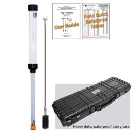
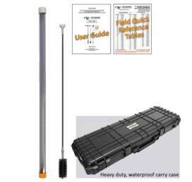
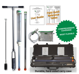
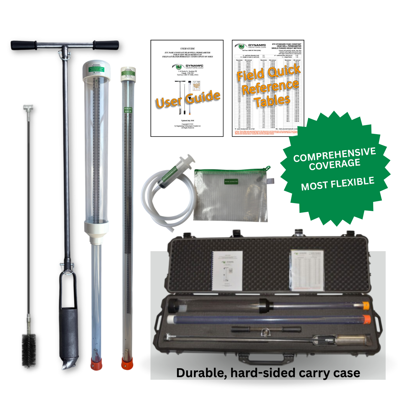
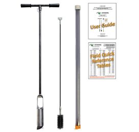
If you have purchased an ETC Pask Permeameter Kit, the kit comes with a set of handy Quick Field Reference Tables for the four major soil capillarity categories. Using the Quick Reference Tables, you will be able to determine the Kfs value in about 10 seconds or less.
Alternatively, if you are using a different auger diameter, or well height, our Spreadsheet for Calculating Kfs does all the calculations below for you.
Example of calculating Kfs by hand from first principles:
The soil type as determined from examination of a test pit near to the permeability test location is a sandy loam with a weak blocky structure.
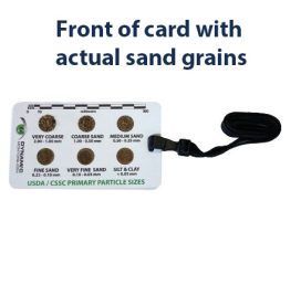
Table 2.1: Texture – Structure Categories for Visual Estimation of a*
|
TEXTURE – STRUCTURE CATEGORY |
Soil Capillarity Category |
a* (cm-1) |
|
Coarse and gravelly sands; may also include some highly structured soils with large cracks and /or macropores. |
Weak |
0.36 |
|
Most structured and medium textured materials; including structured clayey and loamy soils, as well as unstructured medium single-grain sands. This category is generally the first choice for most soils. |
Moderate |
0.12 |
|
Porous materials that are both fine textured and massive; including unstructured clayey and silty soils, as well as very fine to fine structureless sandy materials. |
Strong |
0.04 |
|
Compacted, structureless, clayey materials such as landfill caps and liners, lacustrine or marine sediments. |
Very Strong |
0.01 |
Source: Adapted from Reynolds, W.D., (2008) and Reynolds et al (2015).
Based on a visual assessment of the soil capillarity category, from Table 2.1 (above) we select:
a* = 0.12 cm-1
From the field permeameter test, the quasi steady state rate of fall (R) was determined to be:
R = 0.20 cm/min
The completed well hole diameter is 8.3 cm.
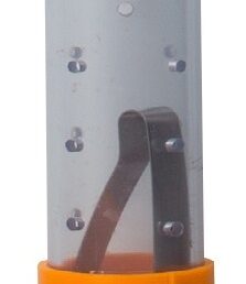
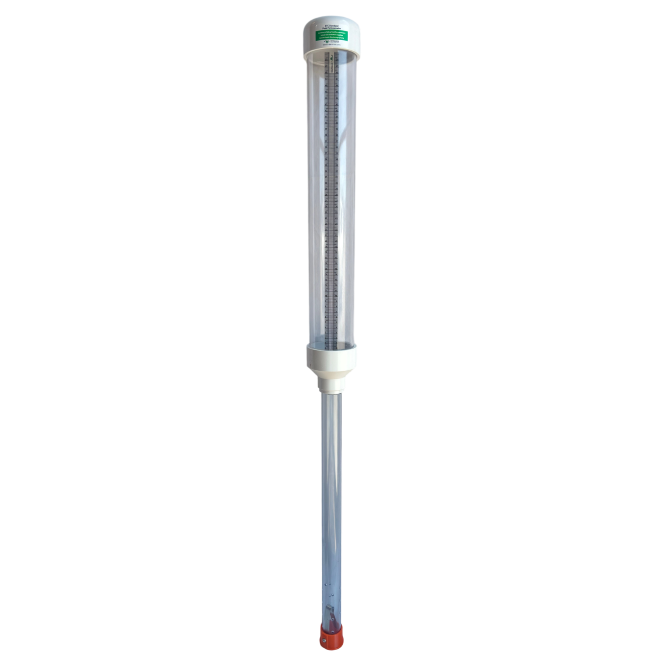
For the ETC Pask Permeameter:
X = Reservoir cross sectional area = 53.46 cm2 (inside diameter is 8.25 cm)
H = Height of constant head in well=15 cm (from bottom of the cap to the air inlet hole)
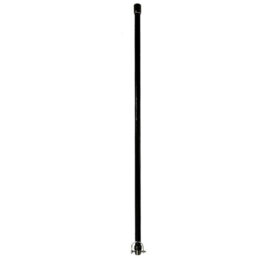
For the AMS Riverside auger, the typical well hole diameter = 8.3 cm, therefore a = 4.15 cm (well hole radius)
Calculating:
H/a = 15/4.15 = 3.61
Therefore, from the C Factor Chart, we can determine that:
C = 1.36 (for a* = 0.12 cm-1)
Calculating:
Q = XR = 53.46 x 0.20 = 10.69 cm3/min
Calculate Kfs using Equation 1:
Kfs = CQ / [2pH2 +Cpa2 + (2pH/a*)]
Where formula constants are grouped and named as “A” and “B”:
A = 2pH2/C +pa2 B = 2pH/C
Therefore, to calculate the field saturated hydraulic conductivity:
Kfs = Q/(A + B/a*)
Calculating:
A = (2p152)/1.36 + p4.152 = 1093.60cm2
B = (2p15)/1.36 = 69.30cm2
Finally calculating:
Kfs = Q/(A + (B/a*)
Kfs = 10.69/(1093.60+69.30/0.12) cm/min
Kfs = 6.3 x 10⁻³ cm/min
Kfs = 1.1×10⁻⁶ m/sec
References:
Reynolds,W.D. and Galloway, K.A. and Radcliffe, D.E. 2015. The relationship between perc time and field-saturated hydraulic conductivity for cylindrical test holes. Proceedings of the Annual Conference of the National Onsite Wastewater Recycling Association, West Virginia Beach, West Virginia. November 2015.
Reynolds,W.D. 2008, Saturated Hydraulic Properties: Well Permeameter. In Carter, M.R. and Gregorich, E.G. (Eds.), Soil Sampling and Methods of Analysis (2nd ed.). Canadian Society of Soil Science. CRC Press, Boca Raton, FL., USA, pp. 1025-1042.
Please note the spreadsheet is protected by Copyright. You are purchasing a single user license for this spreadsheet program. Therefore, it may not be sold or distributed to other third parties, inside or outside of our organization, or installed on the computer of more than one user at a time, or on a network accessible by more than one user, without the express written permission of Dynamic Monitors.


Reviews
There are no reviews yet.